Loop / Loop Node
Embedded Engineer lets you model loops in activities in two different ways, namely as a construct with decision/merge nodes, or with a structured activity. First, we'll outline the traditional loop.
Traditional Style
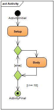
 This works just as expected. The upper node is a
 merge node, the lower a decision node.
When modeling loops in this way, please make sure that there is exactly one incoming edge to the loop, and that this incoming edge targets a merge node.
In this case, the edge coming from Setup is the entry to the loop.
Also make sure that there's exactly one outgoing edge from the loop, and that this outgoing edge originates at the decision node of the loop.
Here, the edge with the guard i >= 10 is the exit from the loop.
As long as these two conditions are met everything is fine. If the control flows form a structure which can't be recreated with if and while statements, Embedded Engineer will detect this and point you to the control flow which is most likely the culprit.
You can also nest the loops to whatever level you'd like, but keep in mind that nested loops tend to be hard to understand and also to maintain.
Structured Style
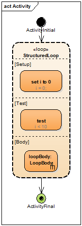
 Another way to model loops are the so called
 structured activity loops.
You can add them to your diagram by clicking on Structured Activity in the toolbox, and clicking on the activity diagram afterwards.
There you can select Loop Node which will add a loop to your diagram. This loop behaves like the loop before:
First, the nodes in the setup are called.
Then, if it's a tested-first-loop (analogous to a while-loop in C), the test will be called to determine if the loop body should execute, followed by a call of the loop body and so on.
If it's a test-last-loop (analogous to a do-while loop in C), the test will be executed after the call to the body.

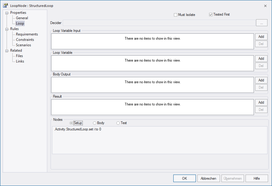
The picture above shows the preferences of the Loop Node, in which you can select if it's handled as Tested First or Tested Last loop.
At the bottom of the dialog, you can see which activity nodes (i.e. actions) belong to the different parts of the loop.
Note
There are no initial nodes in the structured loop. In fact, there must not be any initial nodes.
Also, each section must have exactly one node without incoming edges. This node will be called first, and through control flows, subsequent nodes may be called after that.
For Loop
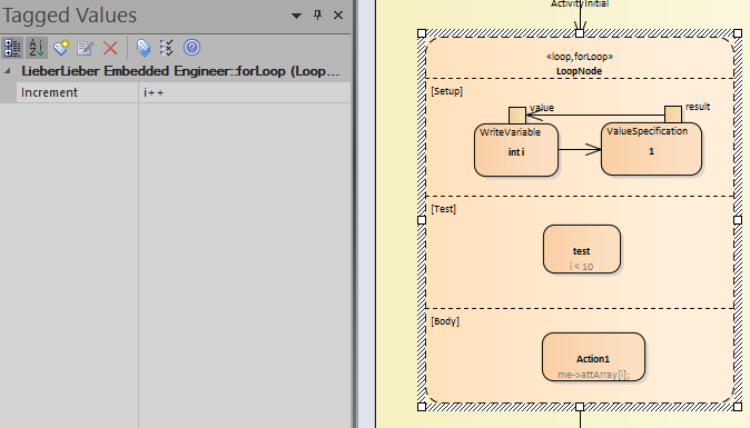
A Structured Activity - Loop Node will by default generate a while loop, if it gets extended with the for loop Stereotype the generation will be changed to write a for loop.
Additionally the Loop Node will get an Increment Tagged Value where the incrementation value (e.g.: i++ or i–) needs to be added.
The Setup section can be used with a WriteVariable and ValueSpecification action to initialize the for-loop (see illustration).

/* Comment for forLoop */
for (int i = 1; i < 10; i++)
{
    /* SyncableUserCode{5CE259DB-20C0-40af-BEDA-BC2B6E77A96D}:uqtoKEU5GH */
    me->attArray[i];
    /* SyncableUserCode{5CE259DB-20C0-40af-BEDA-BC2B6E77A96D} */
}
Warning
For various reasons it can happen that not all nodes are correctly assigned to the proper parts of the loop. If this happens, try to move the respective nodes out of the loop and into the loop again. Save the diagram, close it and re-open it. The nodes should now appear in the correct parts of the loop.
Uml 2.4.1 - 12.3.35 LoopNode
Please consider that Uml 2.4.1 - 12.3.35 LoopNode specifies that setup, body and test are lists of ExecutableNodes.
Therefore you can not use Decisions (or other ControlNodes) as the first/inital node inside these parts.
Info
Strutured Style loop will only consider Opaque-, CallOperation-, CallBehavior- and SendSignal Actions to be the "starting point".
This way ValueSpecification-, Read/WriteVariable- and other Actions do not need to be overly constraint with a ControlFlow and Embedded Engineer will still generate executable code.