Restrictions
Embedded Engineer generates efficient code for state machines. Therefore, please read this chapter on what restrictions apply which must be taken into account when modeling state machines.
Submachines
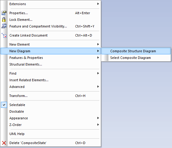
Instead of submachines, please use the semantically equivalent composite state, as submachines are not supported by Embedded Engineer. To increase the readability of the diagram, you can add a diagram to a state. To do so, select the state and open the context-menu, then navigate to New Diagram and Composite Structure Diagram. The resulting state can be used exactly like a submachine.
Run To Completion
State Machine code generated with Embedded Engineer performs at most one step (transition) for every invocation, and will not fire so called completion events. The return value of the state machine method can be used to check if a transition was performed. If you want your state machine to run as long as a transition is active, please use this code to call your state machine (adjust the class and state machine names according to your project):
Implementation example
int evConsumed = 0;
evConsumed = Class_STM(&myClass, &(myClass.STM), sig);
while(evConsumed) {
    evConsumed = Class_STM(&myClass, &(myClass.STM), NOSIG);
}
This will send the NOSIG signal, which is not attached to any triggers, until it hasn't been handled anymore, effectively running the state machine to its next stable state. Keep in mind that this can lead to unexpected run-time characteristics and even infinite loops, so be very careful when using this method to run the state machine.
Initial Nodes
There's no support for an implicit initial node. There must be exactly one initial node for every composite state (and for the main state machine), except when there are no transitions to the containing composite state. According to this, these state machines are valid:
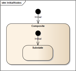
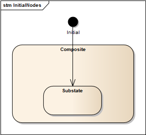
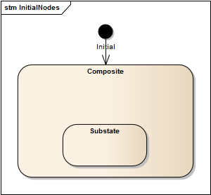
But this state machine violates the rule and will cause an error in the code generation:
Naming
State names must be unique for a single state machine. Only final states and pseudo states are exempt from this rule, because pseudo states are not visible in the code and the names of final states will be generated by the code generator. Also note that the state name is used as an identifier in the generated code. Make sure that your state names are also valid identifiers in C. Please refrain from using a state name more than once in a given state machine. The code generator will produce an error if you use the same name in a state machine more than once. As noted before, this rule does not apply to final states and pseudo states.
Unsupported Elements
Code generation for state machines currently does not support the following elements:
- Regions
- Fork/Join/Synch
- Submachines (although you can use composite states for that: Submachines)
- Information flow
- Terminate pseudo states
- Change triggers
- Call triggers
- Deferred events
Completion transitions and completion events
When generating code for Statemachines such as in the model below the test == 1 transition will be missing from the generated code.
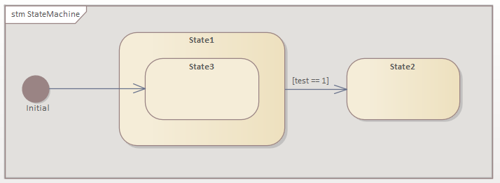
This is due to the Completion transitions and completion events defined in the UML Superstructure 2.4.1.
UML Superstructure 2.4.1
...A completion transition is a transition originating from a state or an exit point but which does not have an explicit trigger, although it may have a guard defined. .... If the state is a composite state or a submachine state, a completion event is generated if either the submachine or the contained region has reached a final state and the state’s internal activities have been completed. This event is the implicit trigger for a completion transition. ...
Therefore Embedded Engineer will omit the generation of the test == 1 Transition since State1 is still active since State3 was not deactivated/exited.